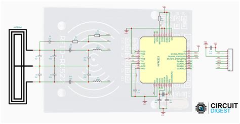
rfid reader diagram In this tutorial, we discussed how the RFID Reader Module works and how we can use it with Arduino. For Interfacing RFID Reader Module RC522 with Arduino, we have provided Circuit Connection, Arduino Code, and a step-by-step guide. The NFC Reader Mode is a powerfull way to communicate with NFC tags. For most use cases it is more reliable and more easy to use, compared to the (older) Intent-based way.
0 · types of rfid readers
1 · rfid stands for in computer
2 · rfid schematic diagram
3 · rfid is involved when using
4 · rfid full form in computer
5 · rfid circuit diagram explanation
6 · block diagram of rfid tag
7 · block diagram of rfid system
Here are some of my favorite creative ways to use NFC tags with your iPhone. 1. Instantly connect to a Wi-Fi network. One of the biggest pains of living in the digital age is remembering complicated passwords. NFC can .
In this tutorial, we discussed how the RFID Reader Module works and how we . Any RFID System will consist of a RFID reader and a RFID tag. The tag will often be small and portable with little to no electronics in it. We will learn more about the tags later in this article, a simple RFID system can be .RFID uses radio waves produced by a reader to detect the presence of (then read the data stored on) an RFID tag. Tags are embedded in small items like cards, buttons, or tiny capsules. These readers also use radio waves in some systems to write new information to the tags.
In this tutorial, we discussed how the RFID Reader Module works and how we can use it with Arduino. For Interfacing RFID Reader Module RC522 with Arduino, we have provided Circuit Connection, Arduino Code, and a step-by-step guide.
Any RFID System will consist of a RFID reader and a RFID tag. The tag will often be small and portable with little to no electronics in it. We will learn more about the tags later in this article, a simple RFID system can be represented using the below block diagram. Block diagram of a RFID system.RC522 RFID Reader Module Pinout diagram, Pin Configuration details, Interfacing with Arduino Example, Applications, Features, Datasheet.Reader: A reader captures the data provided by the tag within the detectable area of the Reader. There can be one or more tags within the capture area. A reader is typically capable of reading multiple tags simultaneously.
All modern RFID reader ICs take care of the entire RF front-end (excepting the antenna) and handle all of the modulation and message passing. The IC's interface is entirely digital using a conventional parallel or serial bus. Texas Instruments’ TRF7970ARHBT, whose block diagram is shown in Figure 4, is a typical reader IC.The RFID reader consists of transmitting and receiving sections. It transmits a carrier signal (13.56 MHz), receives the backscattered signal from the tag, and performs data processing. The reader also communi-cates with an external host computer. A basic block dia-gram of a typical RFID reader is shown in Figure 2-1. RFID (Radio Frequency Identification) reader circuit diagrams are used in a variety of applications for tracking and identifying objects. Every RFID system has at least one RFID reader, which is the device that reads the information from the RFID tag.Designing an RFID reader circuit involves understanding the principles of RFID technology, selecting the right components, and implementing them correctly. By following the steps outlined in this guide, you can create a custom RFID reader circuit tailored to your specific application.
In this tutorial, we learn how to interfacing RFID with an Arduino. An RFID Sensor, which is a Radio Frequency Identification Reader, gathers data from a card with an RFID tag. An RFID reader reads RFID tags. It transfers data from the card tag to an RFID reader using radio waves.
types of rfid readers

RFID uses radio waves produced by a reader to detect the presence of (then read the data stored on) an RFID tag. Tags are embedded in small items like cards, buttons, or tiny capsules. These readers also use radio waves in some systems to write new information to the tags. In this tutorial, we discussed how the RFID Reader Module works and how we can use it with Arduino. For Interfacing RFID Reader Module RC522 with Arduino, we have provided Circuit Connection, Arduino Code, and a step-by-step guide.
difference between rfid and mifare card
Any RFID System will consist of a RFID reader and a RFID tag. The tag will often be small and portable with little to no electronics in it. We will learn more about the tags later in this article, a simple RFID system can be represented using the below block diagram. Block diagram of a RFID system.RC522 RFID Reader Module Pinout diagram, Pin Configuration details, Interfacing with Arduino Example, Applications, Features, Datasheet.Reader: A reader captures the data provided by the tag within the detectable area of the Reader. There can be one or more tags within the capture area. A reader is typically capable of reading multiple tags simultaneously.
All modern RFID reader ICs take care of the entire RF front-end (excepting the antenna) and handle all of the modulation and message passing. The IC's interface is entirely digital using a conventional parallel or serial bus. Texas Instruments’ TRF7970ARHBT, whose block diagram is shown in Figure 4, is a typical reader IC.The RFID reader consists of transmitting and receiving sections. It transmits a carrier signal (13.56 MHz), receives the backscattered signal from the tag, and performs data processing. The reader also communi-cates with an external host computer. A basic block dia-gram of a typical RFID reader is shown in Figure 2-1. RFID (Radio Frequency Identification) reader circuit diagrams are used in a variety of applications for tracking and identifying objects. Every RFID system has at least one RFID reader, which is the device that reads the information from the RFID tag.
rfid stands for in computer
Designing an RFID reader circuit involves understanding the principles of RFID technology, selecting the right components, and implementing them correctly. By following the steps outlined in this guide, you can create a custom RFID reader circuit tailored to your specific application.

rfid schematic diagram


diy rfid reader/writer
dell latitude e6400 rfid reader
$42.65
rfid reader diagram|block diagram of rfid system