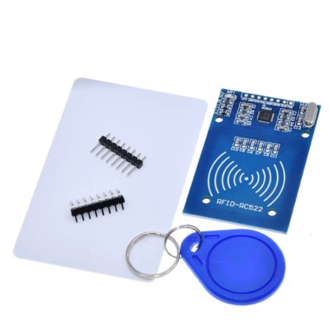
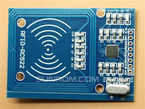
rfid reader module circuit diagram In this tutorial, we discussed how the RFID Reader Module works and how we can use it with Arduino. For Interfacing RFID Reader Module RC522 with Arduino, we have provided Circuit Connection, Arduino Code, and a step-by-step guide. $2.74
0 · rfid tags and readers
1 · rfid reader module v2
2 · rfid reader module price
3 · rfid reader module pdf
4 · rfid reader module arduino
5 · rfid module price
6 · rfid module not scanning card
7 · rfid module datasheet
Posted on Nov 1, 2021 12:10 PM. On your iPhone, open the Shortcuts app. Tap on the Automation tab at the bottom of your screen. Tap on Create Personal Automation. Scroll down and select NFC. Tap on Scan. Put .
EM18 RFID Reader is a module which reads the ID information stored in RFID TAGS. This ID information is unique for every TAG which cannot be copied. EM-18 Pin .

In this tutorial, we discussed how the RFID Reader Module works and how we can use it with Arduino. For Interfacing RFID Reader Module RC522 with Arduino, we have provided Circuit Connection, Arduino Code, and a step-by-step guide.RC522 RFID Reader Module Pinout diagram, Pin Configuration details, Interfacing with Arduino Example, Applications, Features, Datasheet.
EM18 RFID Reader is a module which reads the ID information stored in RFID TAGS. This ID information is unique for every TAG which cannot be copied. EM-18 Pin Configuration. EM-18 is a nine pin device. Among nine pins, 2 pins are not connected, so we basically have to consider seven terminals.
Learn how to use RFID NFC RC522 with Arduino, how to connect RFID-RC522 module to Arduino, how to code for RFID/NFC, how to program Arduino step by step. The detail instruction, code, wiring diagram, video tutorial, line-by-line code explanation are provided to help you quickly get started with Arduino. Find this and other Arduino tutorials on .RFID RC522 Reader Module. RFID card tag and key fob. The RC522 module works on a 13.56 MHz frequency and it can act as a reader and write for UID/RFID cards. The RFID cards communicate with the module at a short distance with radio . Figure #1 – Arduino RFID Reader Circuit Diagram. Components. Arduino UNO [Buy Here] EM – 18 RFID Reader Module. RFID Cards or Tags. 16 x 2 LCD Display [Buy Here] 10KΩ Potentiometer. Connecting wires. Power supply – 5V and 12V. Prototyping board. RFID Reader and RFID Cards. As mentioned earlier, RFID is a wireless, non-contact type technology.
The RC522 RFID reader module is designed to create a 13.56MHz electromagnetic field and communicate with RFID tags (ISO 14443A standard tags). The reader can communicate with a microcontroller over a 4-pin SPI with a maximum data rate of 10 Mbps. It also supports communication over I2C and UART protocols.Circuit Diagram For Interfacing RFID with Arduino. n the circuit diagram for this integration, you’ll typically see the RC522 RFID module connected to specific pins on the Arduino board. These connections allow for data exchange between the RFID reader and Arduino microcontroller. In this tutorial, we are going to interface RDM6300 RFID Reader Module with Arduino Nano. The RDM6300 RFID Reader is one type of RFID module with a 125 kHz frequency. This RFID module can read data from 125 kHz compatible read .
Overview. Components Needed To Build Arduino RFID Project. Hardware Components. Software. Basics of The RFID Technology. What is RFID? What are the features of RFID? What are the applications of RFID? Features of the MFRC522 RFID Front end. Pinout of the RC522 RFID Module. Step-By-Step Instructions To Connect The RFID RC422 With . In this tutorial, we discussed how the RFID Reader Module works and how we can use it with Arduino. For Interfacing RFID Reader Module RC522 with Arduino, we have provided Circuit Connection, Arduino Code, and a step-by-step guide.RC522 RFID Reader Module Pinout diagram, Pin Configuration details, Interfacing with Arduino Example, Applications, Features, Datasheet. EM18 RFID Reader is a module which reads the ID information stored in RFID TAGS. This ID information is unique for every TAG which cannot be copied. EM-18 Pin Configuration. EM-18 is a nine pin device. Among nine pins, 2 pins are not connected, so we basically have to consider seven terminals.
Learn how to use RFID NFC RC522 with Arduino, how to connect RFID-RC522 module to Arduino, how to code for RFID/NFC, how to program Arduino step by step. The detail instruction, code, wiring diagram, video tutorial, line-by-line code explanation are provided to help you quickly get started with Arduino. Find this and other Arduino tutorials on .RFID RC522 Reader Module. RFID card tag and key fob. The RC522 module works on a 13.56 MHz frequency and it can act as a reader and write for UID/RFID cards. The RFID cards communicate with the module at a short distance with radio .
rfid tags and readers
Figure #1 – Arduino RFID Reader Circuit Diagram. Components. Arduino UNO [Buy Here] EM – 18 RFID Reader Module. RFID Cards or Tags. 16 x 2 LCD Display [Buy Here] 10KΩ Potentiometer. Connecting wires. Power supply – 5V and 12V. Prototyping board. RFID Reader and RFID Cards. As mentioned earlier, RFID is a wireless, non-contact type technology.The RC522 RFID reader module is designed to create a 13.56MHz electromagnetic field and communicate with RFID tags (ISO 14443A standard tags). The reader can communicate with a microcontroller over a 4-pin SPI with a maximum data rate of 10 Mbps. It also supports communication over I2C and UART protocols.Circuit Diagram For Interfacing RFID with Arduino. n the circuit diagram for this integration, you’ll typically see the RC522 RFID module connected to specific pins on the Arduino board. These connections allow for data exchange between the RFID reader and Arduino microcontroller. In this tutorial, we are going to interface RDM6300 RFID Reader Module with Arduino Nano. The RDM6300 RFID Reader is one type of RFID module with a 125 kHz frequency. This RFID module can read data from 125 kHz compatible read .
nfc tags android automate
nfc tag type not supported j5
rfid reader module v2

rfid reader module price

A contactless card can also be referred to as a “dual interface” card – simply .
rfid reader module circuit diagram|rfid tags and readers