rfid based security system using pic16f877a This system is designed around PIC microcontroller PIC16F877A and RFID Reader RDM6300, which is 125 kHz reader. It also features LCD 1602 display, a buzzer, servo SG90 and a . Bluetooth NFC readers are somewhat less common than USB ones, but there are still several available on the market. Prior to the adoption of USB-C, these were your only options for broad tablet compatibility if it was necessary to charge the tablet while using the reader. . Exacerbating this issue is the fact that the Android Bluetooth driver .
0 · pic16f877a rfid
1 · pic16f877a interfacing circuit diagram
NFC tags and readers communicate wirelessly with each other over very short distances. Tags store a small amount of data on them that is sent to the reader in the form of electromagnetic pulses .
An automated door lock/unlock system capable of user verification through two methods: RFID and Keypad. The system also has the capability to store new user data, enabling .This system is designed around PIC microcontroller PIC16F877A and RFID Reader RDM6300, which is 125 kHz reader. It also features LCD 1602 display, a buzzer, servo SG90 and a voltage regulating part.An automated door lock/unlock system capable of user verification through two methods: RFID and Keypad. The system also has the capability to store new user data, enabling . Here we are using PIC Microcontroller PIC16F877A for interfacing RFID. We will simply read the unique identification no. of RFID tags using UART serial communication and .
This system is designed around PIC microcontroller PIC16F877A and RFID Reader RDM6300, which is 125 kHz reader. It also features LCD 1602 display, a buzzer, servo SG90 and a . It can be directly interfaced with microcontrollers using UART and with PC using an RS232 converter. Just power the module, and it will read any RFID card within range. It will .This project utilizes PIC Microcontroller PIC16F877A that integerates, deploy and collect Real Time voting decisions using RFID Tags.This is a project for a smart home system using PIC16f877A microcontroller. The system is designed to control home for ease of life and happiness. The system includes an RFID-based .
This project showcases two methods to use a functional keypad accessed security system for hotel rooms, implemented using a PIC microcontroller and programmed in C,C++. The system . To address this, we have developed a Smart Door Lock System that utilizes both RFID technology and keypad functionality, powered by the advanced PIC16F877A . Here we are using PIC Microcontroller PIC16F877A for interfacing RFID. We will simply read the unique identification no. of RFID tags and display it on 16×2 LCD. RFID . This paper presents a design of RFID-based home emergency and notification system with GSM, 3G video servises and two way radio functionalities for .
An automated door lock/unlock system capable of user verification through two methods: RFID and Keypad. The system also has the capability to store new user data, enabling . Here we are using PIC Microcontroller PIC16F877A for interfacing RFID. We will simply read the unique identification no. of RFID tags using UART serial communication and .This system is designed around PIC microcontroller PIC16F877A and RFID Reader RDM6300, which is 125 kHz reader. It also features LCD 1602 display, a buzzer, servo SG90 and a .
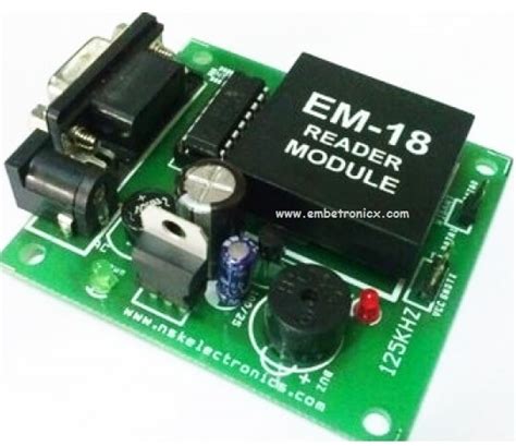
It can be directly interfaced with microcontrollers using UART and with PC using an RS232 converter. Just power the module, and it will read any RFID card within range. It will .
pic16f877a rfid
This project utilizes PIC Microcontroller PIC16F877A that integerates, deploy and collect Real Time voting decisions using RFID Tags.This is a project for a smart home system using PIC16f877A microcontroller. The system is designed to control home for ease of life and happiness. The system includes an RFID-based .This project showcases two methods to use a functional keypad accessed security system for hotel rooms, implemented using a PIC microcontroller and programmed in C,C++. The system .
To address this, we have developed a Smart Door Lock System that utilizes both RFID technology and keypad functionality, powered by the advanced PIC16F877A . Here we are using PIC Microcontroller PIC16F877A for interfacing RFID. We will simply read the unique identification no. of RFID tags and display it on 16×2 LCD. RFID .
pic16f877a interfacing circuit diagram

Transfer your Amiibo character saves to the Power Tag within seconds or use it to try out new .
rfid based security system using pic16f877a|pic16f877a interfacing circuit diagram