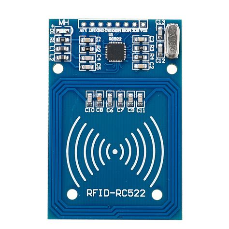
rfid reader schematic datasheet RFID reader is used to activate passive tag with RF energy and to extract information from the tag. For this function, the reader includes RF transmission, receiving and data decoding sections. Contactless payments are transactions made by tapping either a contactless .
0 · rfid reader module rc522
1 · rfid reader module pinout
2 · rfid antenna circuit diagram
3 · rfid 125khz
4 · rc522 rfid module pinout
5 · microid rfid circuit diagram
6 · microid 125 rfid system
7 · arduino rfid reader module
5. Minnesota Vikings (7-2) Minnesota is the No. 5 seed in the NFC, trailing Detroit by a game for the division lead. The Vikings are the top wild-card team in the conference.
RFID reader is used to activate passive tag with RF energy and to extract information from the tag. For this function, the reader includes RF transmission, receiving and data decoding sections.The ATA5577C is a contactless read/write Identification Integrated Chip (IDIC®) for applications in the 125 kHz or 134 kHz frequency band. A single coil connected to the chip serves as the IC’s power supply and bidirectional communication interface.RFID reader is used to activate passive tag with RF energy and to extract information from the tag. For this function, the reader includes RF transmission, receiving and data decoding sections.RC522 RFID Reader Module Pinout diagram, Pin Configuration details, Interfacing with Arduino Example, Applications, Features, Datasheet.
The MCRF355 and MCRF360 are Microchip’s 13.56 MHz microID® family of RFID tagging devices. They are uniquely designed read-only passive Radio Frequency Identification (RFID) devices with an advanced anti-collision feature. They .RC522 RFID Development Kit ommunication at 13.56 MHz. The MFRC522 reader supports ISO/I C 14443 A/MIFARE and NTAG. The MFRC522’s internal transmitter is able to drive a reader/ writer antenna designed to communicate with ISO/IEC 14443A cards and transponders without aThe RFID Reader hardware is based on the EM4095 transceiver IC which drives a printed antenna to communicate with the tag. The EM4095 RFID Reader is connected to the computer via an USB interface.This document describes the functionality and electrical specifications of the contactless reader/writer MFRC522. Remark: The MFRC522 supports all variants of the MIFARE Mini, MIFARE 1K, MIFARE 4K, MIFARE Ultralight, MIFARE DESFire EV1 and MIFARE Plus RF identification protocols.

RDM6300 125KHz RFID Card Reader Module. RDM6300 125KHz RFID card reader module is designed for reading code from 125KHz card compatible read-only tags and read/write card . It can be applied in office/home security, personal identification, access control, anti-forgery, interactive toy and production control systems etc. Work at frequency of .The MFRC522’ s internal transm itter is able to drive a reader/wr iter antenna designed to communicate with ISO/IEC 14443 A/MIF ARE card s and transponders without additionalThis document describes the functionality and electrical specifications of the contactless reader/writer MFRC522. Remark: The MFRC522 supports all variants of the MIFARE Mini, .The ATA5577C is a contactless read/write Identification Integrated Chip (IDIC®) for applications in the 125 kHz or 134 kHz frequency band. A single coil connected to the chip serves as the IC’s power supply and bidirectional communication interface.
RFID reader is used to activate passive tag with RF energy and to extract information from the tag. For this function, the reader includes RF transmission, receiving and data decoding sections.RC522 RFID Reader Module Pinout diagram, Pin Configuration details, Interfacing with Arduino Example, Applications, Features, Datasheet.
The MCRF355 and MCRF360 are Microchip’s 13.56 MHz microID® family of RFID tagging devices. They are uniquely designed read-only passive Radio Frequency Identification (RFID) devices with an advanced anti-collision feature. They .RC522 RFID Development Kit ommunication at 13.56 MHz. The MFRC522 reader supports ISO/I C 14443 A/MIFARE and NTAG. The MFRC522’s internal transmitter is able to drive a reader/ writer antenna designed to communicate with ISO/IEC 14443A cards and transponders without aThe RFID Reader hardware is based on the EM4095 transceiver IC which drives a printed antenna to communicate with the tag. The EM4095 RFID Reader is connected to the computer via an USB interface.This document describes the functionality and electrical specifications of the contactless reader/writer MFRC522. Remark: The MFRC522 supports all variants of the MIFARE Mini, MIFARE 1K, MIFARE 4K, MIFARE Ultralight, MIFARE DESFire EV1 and MIFARE Plus RF identification protocols.
RDM6300 125KHz RFID Card Reader Module. RDM6300 125KHz RFID card reader module is designed for reading code from 125KHz card compatible read-only tags and read/write card . It can be applied in office/home security, personal identification, access control, anti-forgery, interactive toy and production control systems etc. Work at frequency of .The MFRC522’ s internal transm itter is able to drive a reader/wr iter antenna designed to communicate with ISO/IEC 14443 A/MIF ARE card s and transponders without additional
alight smart-choice card atm
rfid reader module rc522
rfid reader module pinout
rfid antenna circuit diagram

They’re behind a Kickstarter campaign for the ChameleonMini, a device for NFC security analysis that can also clone and emulate contactless cards. While the original Chameleon smart card .A customer today in my shop had a NFC Smart bank card that had multiple bank cards on it that you can switch using a mobile phone app & I presume it connected to the phone using .
rfid reader schematic datasheet|microid rfid circuit diagram